
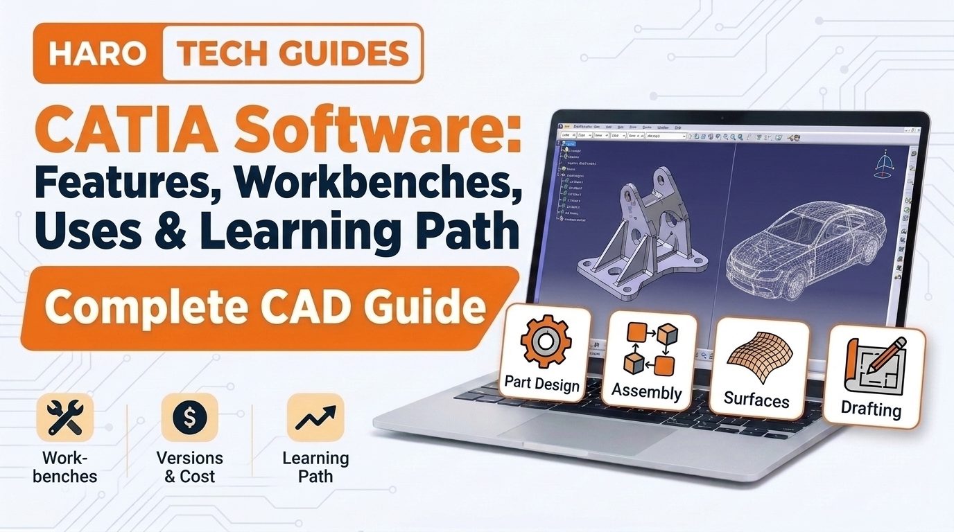
A junior engineer joins an aircraft supplier and finds one strange program open on every desk. That program is CATIA software, and it sits behind many cars, jets, and machines people use daily. New users often compare it with lighter tools such as rhino software and question its higher price.
This guide explains what CATIA is, how its workbenches function, and which industries depend on it most. It also covers the main versions, system needs, licensing, common mistakes, and a practical learning plan for beginners.
Quick Answer: What Is CATIA Software?
CATIA software is a professional 3D design and engineering application developed by the French company Dassault Systèmes. Engineers use it to model parts, build assemblies, shape complex surfaces, and produce manufacturing drawings. Aerospace and automotive firms rely on it heavily, but its price usually suits large teams over hobbyists.
What Does CATIA Stand For?
CATIA stands for Computer Aided Three Dimensional Interactive Application, a name that reflects its original purpose. Dassault Aviation built the first version in the late 1970s to design fighter aircraft. Dassault Systèmes later took over development and turned the tool into a commercial product for many industries.
In simple words, CATIA is a digital workshop where engineers build and test products before manufacturing begins. The program lets teams check fit, form, and function long before anyone cuts metal or molds plastic. That early checking saves money because fixing a digital model costs far less than fixing physical tooling.
| Item | Detail |
|---|---|
| Full name | Computer Aided Three Dimensional Interactive Application |
| Developer | Dassault Systèmes |
| Origin | Dassault Aviation, late 1970s |
| Main users | Aerospace, automotive, industrial equipment |
| Current platforms | CATIA V5 and CATIA on 3DEXPERIENCE |
| Main strength | Complex surfaces and huge assemblies |
The table shows that CATIA grew from aircraft work into a broad engineering platform over four decades.
How Does CATIA Software Work?
CATIA organizes its tools into separate workspaces called workbenches, and each workbench handles one engineering task. A designer opens the Part Design workbench to model a bracket, then switches to Drafting for its drawing. This structure keeps menus focused, so engineers see only the commands that match their current job.
Feature Based Parametric Modeling
CATIA records every modeling step as a feature inside a history tree beside the model. Each feature stores dimensions and rules, so changing one value updates every dependent feature automatically. An engineer who widens a slot by two millimeters sees the holes and fillets around it update instantly.
The Specification Tree
The specification tree lists sketches, pads, pockets, fillets, and other features in the order the designer created them. Users click any feature in the tree to edit its parameters or reorder its position. A clean tree helps colleagues read the design intent months later without asking the original author.
Knowledge Based Engineering
CATIA lets teams add formulas, rules, and checks directly inside a model through its knowledgeware tools. A rule might stop wall thickness from dropping below a safe limit during later edits. These rules turn company standards into automatic checks instead of notes on a forgotten wiki page.
What Are the Main CATIA Workbenches?
CATIA ships with dozens of workbenches, but most engineers spend their days inside a handful of core modules. Each workbench groups related commands, and licenses decide which workbenches a user can open. The table below lists the core modules that most beginners meet during their first weeks.
| Workbench | Main job | Typical output |
|---|---|---|
| Sketcher | 2D profiles with constraints | Sketch geometry |
| Part Design | Solid feature modeling | Single part models |
| Assembly Design | Joining parts with constraints | Product assemblies |
| Generative Shape Design | Advanced surface modeling | Body panels, ducts |
| Drafting | 2D engineering drawings | Dimensioned drawings |
| Generative Sheetmetal Design | Bent metal parts | Flat patterns |
| DMU Kinematics | Motion simulation | Mechanism studies |
Most new users learn Sketcher, Part Design, Assembly Design, and Drafting before touching surface or simulation modules.
Sketcher and Part Design
Sketcher creates 2D profiles with geometric constraints such as parallel lines, equal lengths, and fixed dimensions. Part Design turns those profiles into solids through pads, pockets, shafts, grooves, and holes. Together these two workbenches cover most mechanical parts that small and medium suppliers produce.
Assembly Design
Assembly Design places separate parts into one product and links them with contact, coincidence, and offset constraints. Engineers check clearances, measure distances, and spot clashes between components inside this workbench. A car door assembly, for example, might hold hundreds of parts tied together through these constraints.
Generative Shape Design
Generative Shape Design handles freeform surfaces that solid tools struggle with, such as car hoods and wings. Designers create curves, sweep surfaces, blend edges, and trim shapes until the outer skin looks right. This workbench explains why automotive studios and aircraft makers choose CATIA over lighter modeling packages.
Drafting
Drafting produces 2D drawings with views, sections, dimensions, tolerances, and title blocks for the shop floor. The drawing stays linked to the 3D model, so a model change updates the drawing views. Manufacturing teams still depend on these drawings for inspection, even when they receive full 3D data.
Which Industries Use CATIA Software?
CATIA serves industries that build large, precise, and heavily regulated products with long development cycles. Aerospace and automotive companies form its oldest user base, but the list has grown over time. The table summarizes the main sectors and why each one picks this tool.
| Industry | Common use | Reason for choosing CATIA |
|---|---|---|
| Aerospace | Fuselage, wings, interiors | Surface quality and huge assemblies |
| Automotive | Body panels, powertrain parts | Class A surfacing and supplier exchange |
| Shipbuilding | Hull structures, outfitting | Large structure management |
| Industrial equipment | Machines, tooling | Parametric parts and drawings |
| Architecture | Complex building forms | Freeform geometry control |
| Consumer goods | Product housings | Styling surfaces |
Supplier relationships often decide the choice, because many manufacturers require partners to deliver native CATIA files.
Aerospace Projects
Boeing used CATIA to design the 777 digitally in the early 1990s, a landmark project for aircraft engineering. That program showed how a full digital mockup could cut physical prototypes and reduce assembly errors. Airbus and many defense contractors also run large parts of their engineering on Dassault Systèmes tools.
Automotive Projects
Car makers use CATIA for body structures, interior trim, and exterior surfaces with strict visual quality rules. Studio designers hand early concepts to engineers, who rebuild the surfaces with precise curvature control. Many tier one suppliers keep CATIA seats only because their main customers demand native file delivery.
Architecture and Other Fields
The architect Frank Gehry worked with CATIA based tools to model the curved surfaces of his landmark buildings. Shipyards, rail manufacturers, and consumer product firms also use the software for detailed structures and styling. These users share one need, which is accurate control over complex geometry at large scale.
CATIA V5 vs 3DEXPERIENCE CATIA
Dassault Systèmes offers CATIA in two main forms today, and buyers often confuse them during evaluations. CATIA V5 runs as a traditional desktop application that stores files in folders or a separate data system. CATIA on the 3DEXPERIENCE platform connects modeling with cloud or server based data management and collaboration tools.
| Factor | CATIA V5 | 3DEXPERIENCE CATIA |
|---|---|---|
| Installation | Desktop with local files | Desktop app tied to platform |
| Data storage | Folders or separate PDM | Built in platform database |
| Collaboration | Manual file exchange | Shared online workspace |
| Release naming | V5-6R plus year | Year plus x suffix |
| Typical users | Long running programs | New projects and connected teams |
The comparison shows that the core modeling stays similar, while data handling and collaboration change the most.
When V5 Still Makes Sense
Many companies keep V5 because their programs, templates, and suppliers already depend on its file formats. Moving thousands of legacy files into a new platform takes time, money, and careful testing. Teams in the middle of a long aircraft program usually stay on V5 until that program ends.
When 3DEXPERIENCE Fits Better
Newer teams often prefer the 3DEXPERIENCE version because it combines modeling, data control, and project tracking. Engineers in different countries can open the same design without emailing large files back and forth. Startups and smaller firms sometimes reach it through cloud based packages, depending on regional offers.
CATIA vs SolidWorks vs Other CAD Tools
People often compare CATIA with SolidWorks, Siemens NX, Creo, and Autodesk Inventor before buying a license. Each tool models solid parts well, so the differences appear mostly in surfaces, scale, and price. The table below gives a short summary view of how these tools usually compare.
| Tool | Best known for | Typical buyer |
|---|---|---|
| CATIA | Complex surfaces, huge assemblies | Aerospace and automotive majors |
| SolidWorks | Easy mechanical design | Small and medium manufacturers |
| Siemens NX | Design plus manufacturing | Automotive and machinery firms |
| Creo | Parametric and modular design | Industrial equipment makers |
| Inventor | Mechanical parts and drawings | Smaller engineering teams |
Dassault Systèmes owns both CATIA and SolidWorks, but it positions them for different company sizes and project types.
CATIA vs SolidWorks
SolidWorks offers a gentler learning curve, a lower price, and a huge community of hobbyists and small shops. CATIA offers stronger surface tools, better handling of massive assemblies, and deeper industry specific workbenches. A company making small machine parts usually gets more value from SolidWorks than from CATIA.
CATIA vs Siemens NX
Siemens NX competes directly with CATIA in automotive and aerospace work, especially for manufacturing preparation. NX users often praise its synchronous modeling, while CATIA users value its surface quality and supplier networks. Customer requirements decide the choice more often than feature lists, because file compatibility matters across supply chains.
How Much Does CATIA Software Cost?
Dassault Systèmes and its resellers rarely publish fixed list prices for CATIA licenses on public pages. Cost depends on the role package, the chosen workbenches, the license type, and the region of purchase. A full engineering seat usually costs several times more than a mainstream mechanical design tool.
License Types
Buyers can usually choose between perpetual licenses with yearly maintenance and term based subscriptions on the platform. Node locked licenses tie the software to one machine, while floating licenses let several users share seats. Large firms often mix both types to balance cost against flexibility across departments.
Student and Learning Editions
Dassault Systèmes has offered student editions and learning programs through its education branch for many years. These editions usually cost far less, but they limit commercial use and sometimes restrict file exchange. Students should check the current education offer directly, because terms change between releases and regions.
| Cost factor | What it changes |
|---|---|
| Role or package | Number of workbenches included |
| License type | Perpetual, term, node locked, or floating |
| Region | Reseller pricing and taxes |
| Training | Extra cost for courses and certification |
| Hardware | Workstation and graphics card budget |
Buyers should request a written quote that lists every workbench, because missing modules cause surprise costs later.
What Are the CATIA System Requirements?
CATIA runs on Windows workstations, and Dassault Systèmes publishes certified hardware lists for each release. Large assemblies demand plenty of memory, a fast processor, and a certified professional graphics card. Running CATIA on uncertified gaming hardware often works for learning, but it causes display bugs in production work.
| Component | Practical guidance |
|---|---|
| Operating system | Supported 64 bit Windows release |
| Processor | Recent multi core workstation CPU |
| Memory | 16 GB minimum, 32 GB or more for assemblies |
| Graphics | Certified professional card from the official list |
| Storage | Fast SSD with generous free space |
| Display | Full HD or higher resolution monitor |
Teams should confirm exact numbers on the official certification page for their release before buying hardware.
Benefits of CATIA Software
Engineering managers usually list these benefits when they explain their choice of CATIA:
- Class A surface tools let designers build smooth exterior panels that pass strict visual quality checks.
- Large assembly management lets teams load and review products containing many thousands of separate parts.
- Native file compatibility keeps suppliers connected with aerospace and automotive customers without costly conversions.
- Knowledgeware rules turn company design standards into automatic checks inside every new model.
- Linked drawings update automatically when engineers change the 3D model during later design stages.
- Digital mockup tools reveal clashes and clearance problems before any physical prototype gets built.
These benefits explain the high price, because each one removes costly errors from long product programs.
Practical Example: Designing a Simple Bracket in CATIA
A real example shows how the workbenches connect during an ordinary design task in a small engineering team. The engineer needs an L profile steel bracket with four mounting holes for a conveyor frame. The steps below follow the usual workflow that most engineers repeat daily inside CATIA V5.
Step 1: Create a New Part
The engineer opens a new part file and names it with the company numbering format before adding geometry. Proper naming at this stage prevents duplicate files once the bracket enters the shared data system. The part opens inside Part Design with an empty specification tree and three default planes.
Step 2: Sketch the Profile
The engineer selects the side plane, opens Sketcher, and draws the L outline with simple lines. Constraints then fix the leg lengths, the thickness, and the right angle between both legs. A fully constrained sketch turns green, which tells the designer that no geometry can move unexpectedly.
Step 3: Pad the Sketch
The Pad command extrudes the closed profile to the required bracket width in one quick operation. The specification tree now shows the sketch nested under a pad feature with its stored length value. Changing that value later widens the whole bracket without any need to redraw the profile.
Step 4: Add Holes and Fillets
The Hole command places four mounting holes with standard diameters and positions tied to bracket edges. Edge fillets then round the outer corners, and a larger fillet strengthens the inside bend. Each feature appears in the tree, so reviewers can trace every change in the order it happened.
Step 5: Create the Drawing
The engineer switches to Drafting, inserts front, top, and side views, and adds an isometric view for clarity. Dimensions, hole callouts, material notes, and tolerances complete the drawing before the review meeting. Because the drawing links to the model, any later hole change appears automatically on the sheet.
Step 6: Check and Release
A colleague measures the hole spacing against the conveyor frame inside an assembly before approving the design. The part then moves into the data management system with a released status and revision letter. Purchasing receives the drawing, and the shop starts cutting steel without waiting for clarifications.
Sketch profile -> Pad solid -> Add holes -> Add fillets -> Create drawing -> Review -> Release
This flow repeats for most mechanical parts, with surfaces and simulations added for more complex products.
Who Should Learn CATIA Software?
Mechanical, aerospace, and automotive engineering students gain the most from learning CATIA early in their studies. Employers in those sectors often list CATIA skills directly in job advertisements for design engineers. Product designers who want to move into automotive styling also benefit from strong surface modeling skills.
Hobbyists and small business owners usually find better value in lighter tools with free or cheaper licenses. CATIA rewards people who work on long programs inside large organizations with formal design processes. A student aiming for a car maker should learn it, while a furniture maker might choose something simpler.
Career Paths That Use CATIA
Common job titles include design engineer, CAD engineer, surface modeler, tooling designer, and product data specialist. Aerospace suppliers in France, Germany, the United States, and India hire many CATIA users each year. Salary levels depend on region and experience, so readers should check local job boards for current figures.
How to Learn CATIA Software Step by Step
A structured plan helps beginners avoid the frustration that pushes many students away from CATIA early. The steps below follow the order that most training centers use with new engineers.
Step 1: Learn the Interface
Spend the first sessions learning the toolbar layout, mouse controls, the compass, and the specification tree. Comfort with moving around the screen makes every later workbench feel easier and saves hours of confused clicking. Simple exercises such as rotating, panning, and zooming around sample parts build that comfort quickly.
Step 2: Master Sketcher Constraints
Practice drawing fully constrained sketches until green geometry becomes a habit instead of an accident. Poor sketches cause most beginner failures later, because unstable profiles break features after small edits. Short daily drills with ten simple profiles build this skill within two or three weeks.
Step 3: Build Parts in Part Design
Model common mechanical parts such as shafts, flanges, brackets, and housings from printed practice drawings. Each exercise should follow a clear feature order that another engineer could read and edit later. Comparing finished models with the drawings shows where dimensions or design intent went wrong.
Step 4: Combine Parts in Assemblies
Join several practice parts into simple products such as a vise, a pulley, or a small gearbox. Constraint practice teaches how parts relate to each other and how clashes appear during reviews. These small assemblies prepare learners for the huge products they will meet inside real companies.
Step 5: Produce Drawings
Create full drawings with views, sections, dimensions, and notes for every practice part and assembly. Drawing practice reveals modeling mistakes, because poor features produce strange edges and missing dimensions on sheets. Engineering managers often judge new hires by the quality of their first drawings.
Step 6: Add Surfaces and Specialized Modules
Move into Generative Shape Design once solid modeling feels natural and sketches rarely break during edits. Surface skills open doors into automotive styling, aircraft structures, and consumer product design roles. Sheetmetal, composites, and kinematics modules come later, depending on the target industry.
Tips for Working Faster in CATIA
Experienced users share these tips with new team members during their first weeks on the job:
- Name every feature clearly so colleagues can read the specification tree without opening each sketch.
- Fully constrain every sketch before leaving Sketcher to stop features from breaking during later edits.
- Save often and keep backups, because large assemblies sometimes crash on older or uncertified hardware.
- Use company templates for parts and drawings so title blocks and standards stay consistent everywhere.
- Learn the keyboard and mouse shortcuts early, since they save many hours across a long project.
- Keep assemblies light by loading only the parts needed for the current review or design task.
Small habits like these separate productive CATIA users from frustrated ones within the first three months.
Common Mistakes With CATIA Software
New users repeat a familiar set of errors, and most come from rushing the early modeling stages. Avoiding these mistakes saves hours of rework and makes models easier for teammates to edit.
1. Leaving Sketches Underconstrained
Underconstrained sketches let geometry shift when someone edits a dimension elsewhere in the model. Features built on those sketches then fail, and the specification tree fills with red warning icons. Every sketch should turn fully green before the designer creates the next feature.
2. Building Long Messy Trees
Some beginners pile dozens of small features on top of each other without any logical order. These models work at first, but nobody can edit them safely after a few months pass. Grouping features into clear bodies and naming them properly keeps the tree readable for everyone.
3. Ignoring Company Standards
New hires sometimes skip templates, naming rules, and layer settings because they want faster results. Their files then fail data checks, and colleagues waste time fixing title blocks and part numbers. Reading the company CAD manual during the first week prevents most of these problems.
4. Choosing the Wrong Workbench
Beginners often try to build freeform shapes inside Part Design when Generative Shape Design suits the job better. The result usually looks lumpy and breaks when someone changes a single curve later. Picking the right workbench at the start saves rework during every later design change.
5. Skipping Hardware Checks
Teams sometimes install CATIA on unsupported graphics cards and blame the software for constant display glitches. The certified hardware list exists because Dassault Systèmes tests specific drivers with each release. Checking that list before buying workstations prevents months of strange crashes and lost work.
6. Treating CATIA Like a Standalone Tool
Large companies connect CATIA with product data management, manufacturing planning, and business systems. Engineers who ignore those links create files that never reach purchasing, planning, or quality teams correctly. CAD data often feeds enterprise platforms similar to sap erp software, so release discipline matters across the business.
Best Practices for Teams Using CATIA
Successful teams write clear CAD standards that cover naming, templates, units, tolerances, and file storage rules. They review models regularly and coach new members instead of fixing their files silently in the background. Shared libraries of standard parts such as bolts, nuts, and bearings save hours on every project.
Data management deserves the same attention as modeling skills inside any CATIA team. A single source of truth stops engineers from editing old copies and sending wrong revisions to suppliers. Regular training on new releases keeps the team productive as Dassault Systèmes adds features each year.
CATIA Interview Questions for Beginners
Employers often test new candidates with a short set of practical questions during technical interviews. Preparing clear answers to these questions shows real familiarity with the software beyond a quick tutorial.
What Is the Difference Between a Part and a Product?
A part file holds a single component, while a product file holds an assembly of several parts. Interviewers ask this question to confirm that candidates know how CATIA organizes its data. Clear answers mention constraints, instances, and how products reference parts stored in separate files.
What Does a Green Sketch Mean?
A green sketch means every element has full constraints, so no geometry can move without a dimension change. Candidates who explain this point show that they build stable models instead of fragile ones. Strong answers also mention purple overconstrained elements and how to resolve them correctly.
When Should a Designer Use Generative Shape Design?
Designers choose Generative Shape Design for freeform surfaces that solid tools cannot model with enough control. Typical examples include car body panels, aircraft fairings, and ergonomic consumer product housings. Good candidates explain how they convert finished surfaces into solids for manufacturing afterward.
CATIA Software Checklist
Use this checklist before starting a new CATIA project or buying new licenses for a team:
- Confirm which workbenches the project needs before requesting a quote from an authorized reseller.
- Check the certified hardware list for the exact release that the team plans to install.
- Decide between CATIA V5 and the 3DEXPERIENCE version based on customers and supplier requirements.
- Prepare part and drawing templates that follow company naming rules and drafting standards.
- Set up data management so engineers never edit outdated copies of released models.
- Plan structured training for new users before they touch live customer projects.
- Agree on file exchange formats with suppliers who use different CAD systems.
A team that covers these points usually avoids the biggest cost and schedule surprises during rollout.
Frequently Asked Questions
What is CATIA software used for?
CATIA software is used for 3D part modeling, assembly design, surface modeling, and engineering drawings. Aerospace and automotive companies use CATIA to design aircraft structures, car bodies, and complex mechanical systems.
Who makes CATIA software?
Dassault Systèmes, a French software company, develops and sells CATIA software worldwide through direct sales and resellers. The tool started at Dassault Aviation before becoming a commercial product for many industries.
Is CATIA software free?
CATIA software is not free for commercial use, and full engineering seats usually carry high license fees. Students can often access discounted education editions, but those licenses usually limit commercial work.
Is CATIA hard to learn?
CATIA software has a steeper learning curve than SolidWorks or Inventor because of its many workbenches. Most beginners reach basic part and assembly skills within two or three months of steady practice.
What is the difference between CATIA V5 and V6?
CATIA V6 moved data into a platform database, and that line later became CATIA on 3DEXPERIENCE. CATIA V5 stays a desktop application with file based storage that many long programs still use.
Can CATIA run on a Mac?
CATIA software runs natively on Windows workstations, not on macOS, according to the official certification lists. Mac users usually run it through Windows installations, though performance and support depend on the setup.
Which is better, CATIA or SolidWorks?
CATIA software suits large aerospace and automotive programs with complex surfaces and massive assemblies. SolidWorks usually suits smaller manufacturers who need easier modeling at a much lower license cost.
Does CATIA include simulation tools?
CATIA software includes digital mockup, kinematics, and some structural analysis workbenches depending on the license package. Dassault Systèmes also offers SIMULIA products for deeper simulation work on the same platform.
How long does it take to learn CATIA?
Learning CATIA software for basic parts, assemblies, and drawings usually takes two to three months of regular practice. Advanced surface modeling and specialized modules often need another six to twelve months of project work.
Is CATIA still used in 2026?
CATIA software remains a standard tool across aerospace, automotive, and shipbuilding companies in 2026. Dassault Systèmes continues releasing updates for both CATIA V5 and the 3DEXPERIENCE version each year.
Key Takeaways
- CATIA software comes from Dassault Systèmes and started as an aircraft design tool at Dassault Aviation.
- The name stands for Computer Aided Three Dimensional Interactive Application, which reflects its engineering roots.
- Workbenches split the program into focused modules for sketching, parts, assemblies, surfaces, and drawings.
- Parametric features and the specification tree let engineers edit designs without rebuilding entire models.
- Generative Shape Design gives CATIA its strong reputation for smooth automotive and aircraft surfaces.
- Aerospace and automotive companies form the largest user base, with suppliers following customer requirements.
- CATIA V5 uses desktop files, while the 3DEXPERIENCE version stores data inside a connected platform.
- License prices stay private, so buyers must request quotes listing every required workbench and service.
- Certified hardware lists prevent display problems and crashes on production engineering workstations.
- Beginners should master Sketcher constraints before moving into assemblies, drawings, and surface modeling.
- Clear naming, templates, and data management keep large CATIA teams productive across long programs.
Final Thoughts
CATIA software suits engineers and companies that build complex products with demanding surfaces, huge assemblies, and strict suppliers. Its cost and learning curve feel heavy at first, but its tools prevent expensive mistakes on long programs. Students targeting aerospace or automotive careers gain a clear advantage by learning CATIA software early.
Start with the interface and constrained sketches, and then move steadily through parts, assemblies, drawings, and surfaces. Steady practice on realistic parts builds the confidence that employers look for during technical interviews and design reviews.
Explore more software guides on Harobuilder.


💬 Comments 0
No comments yet. Be the first to share your thoughts! 💬
✍️ Leave a Comment